VERY PRELIMINARY
|
||||||

Proposed by
Jean-Marie Frère, ULB, Bruxelles,
with the technical support of
Anastase Karusho , ULB
Thanks to
Jean Tran Thanh Van (ICISE, VietNam)
Trung Quan Tran
Philippe Léonard, ULB
A simple set-up is proposed, suitable for schools or the first years of university.
The goal is to obtain a sufficiently precise measurement to allow for a significant comparison with other groups world-wide.
and collaboration :
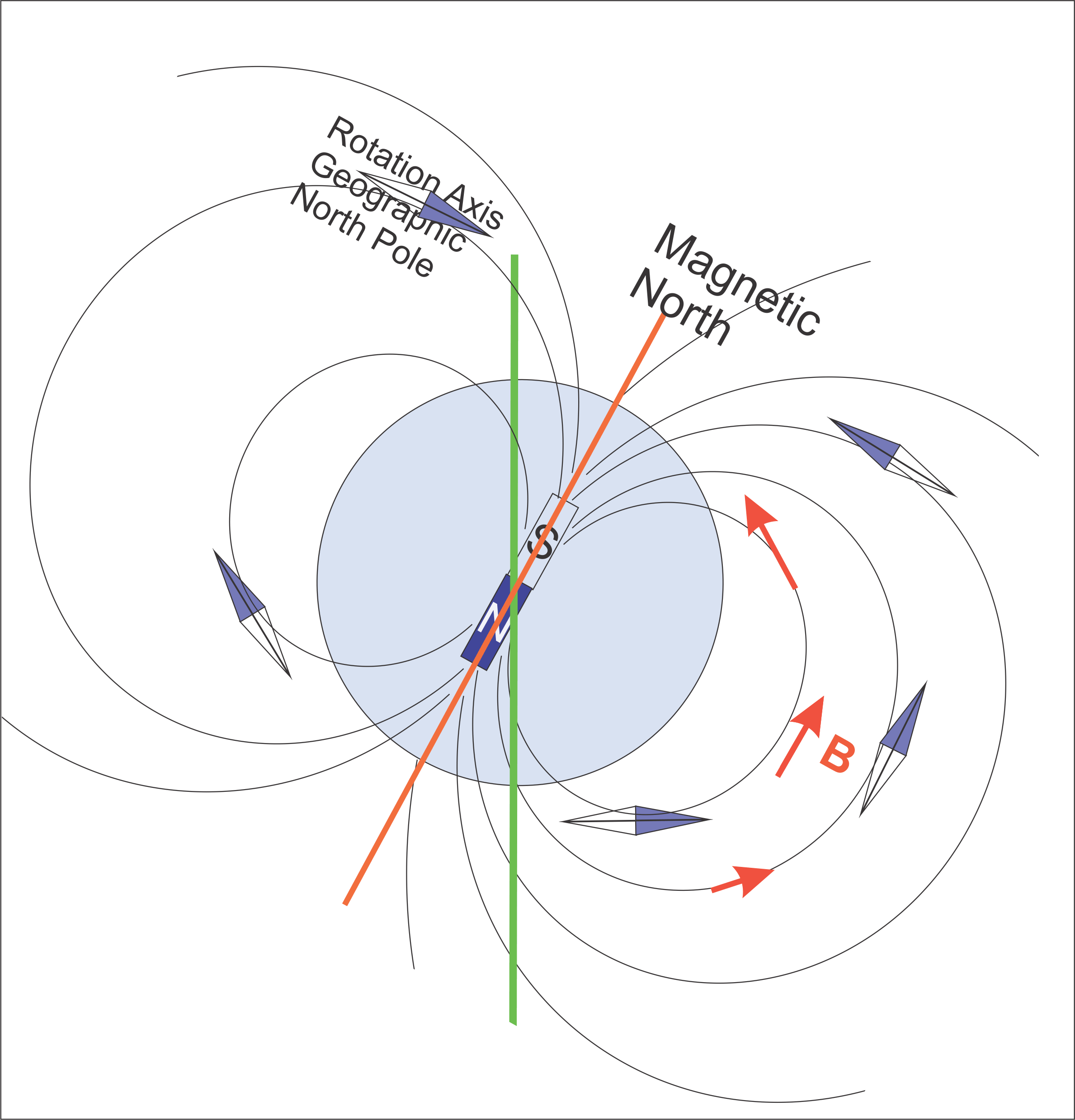
Here is a simple picture, which shows that the intensity of the B field vary around the Earth.
Nearly horizontal in the tropics, the field points sharply downwards at the latitude of Belgium, and upwards in the Southern hemisphere.
Since the proposed measurement is for the horizontal component, sharp differences are expected (see references below, a factor 2 between Belgium and VietNam, for instance).
- A compass is placed inside a coil. The
device is oriented so that the needle is
perpendicular to the coil when no current is
present.
- The current is then increased until an angle
of 45° is reached, at which point, the coil magnetic
field equals in length the horizontal component of
the Earth's magnetic field.
For the 8mm spacing solenoid, we get

If we adjust I to get a 45° angle, we get
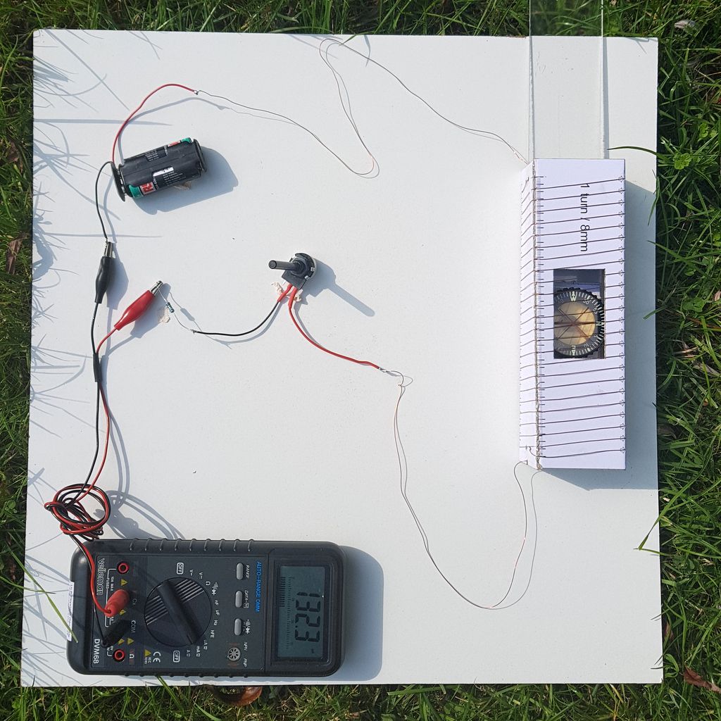
In Brussels, we measured (on Sept 15th, 2017) I = 132 mA, which yields


- The value obtained is compared to international standards, an entered into a collaborative project.
- The measurement may also be compared with
the one obtained from a "smartphone" (less
demonstrative, does not replace the actual
experiment, and calibration is not guaranteed ....).
- A good compass (preferably liquid-filled),
- A few meters (depends on coil chosen: 6 to
12 meters) of copper wire
(insulated or not; magnet/enameled copper wire is ideal but not necessary,
... don't forget to remove the enamel on the ends! )
- a digital multimeter (standard
lab/electrician equipment)
- a variable resistor (e.g. 50 or 100
ohm potentiometer), (or a choice of fixed
resistors for optional method)
- dry cell(s) (small batteries) as a
power supply. we use 2 reloadable AA cells,
but this is not critical .. DO NOT USE a car battery
(a short circuit can cause fatal wounds !)
- some cardboard, glue, ..
- a printed version of the proposed templates
(available here
for 8 mm pitch
and here for 4 mm pitch) -- be sure to check that the printer prints real size (you may need to disable the "shrink to fit" option)-- or design you own!
- If you want to perform a local calibration (not
necessary if you use the templates) , some standard lab
equipment is needed: oscilloscope, LF sine
generator. It is also possible to use a Hall
effect probe.
- assemble the solenoid: print out the chosen
template
(available here for 8 mm pitch and here for 4 mm pitch) making sure that the printer reproduces the correct size (you may need to de-select a "shrink to fit" option) and glue it to some strong cardboard,
then fold and glue it into shape.
- wind your wire according to the notches (it
helps to make an incision with a cutter at each of
the small arrows, so that the wire is trapped in
position)
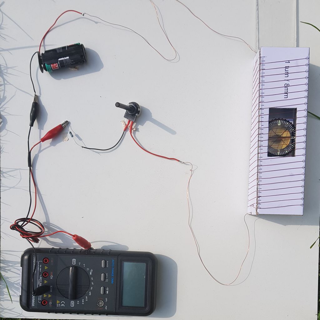
- on a non-magnetic support (wood, cardboard,
plastic) support, assemble the circuit according to
the picture. Here a variable resistor of 100 ohm is
used, as well as 2 reaodable Nimh AA cells (at the
difference of alkaline battery, they have a voltage
of 1.25V each thus a 2.5 V total). You may
need to adapt to your local field (for instance,
using the 4mm pitch to get a lager field).
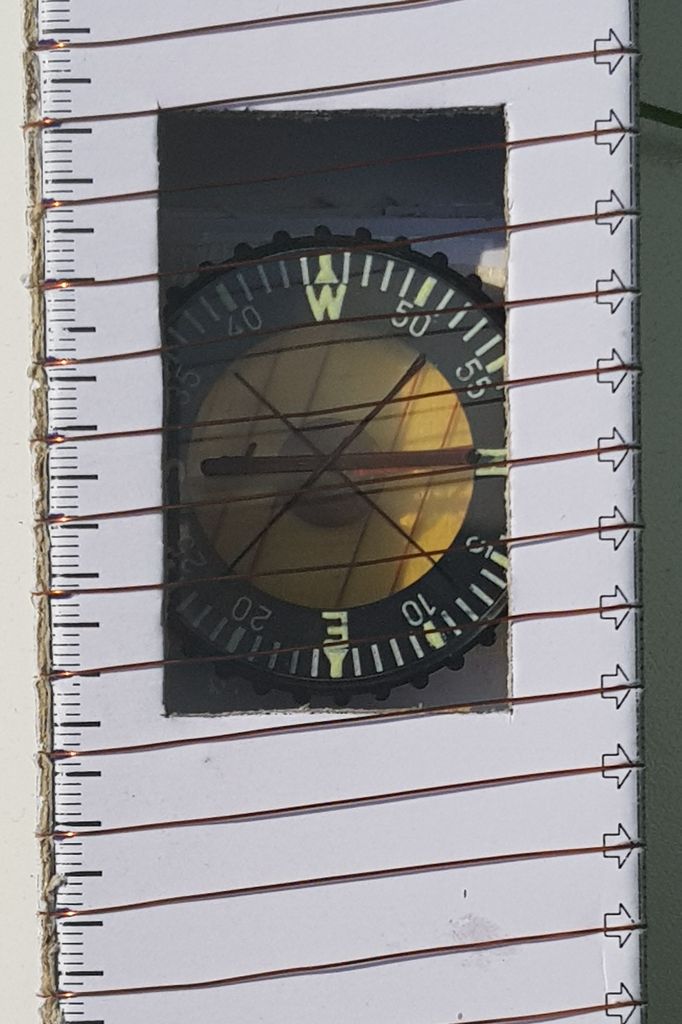
- mark the N-S direction with a felt tip on
the compass housing, repeat for the 45 degrees
direction; insert the compass in the solenoid, so
that N-S markings point perpendicular to the
solenoid axis
- go outdoors, and move away from buildings and possible distortions of the magnetic field
- orient your device so that the needle (in
absence of current) points perpendicular to the
solenoid axis (this means that the axis will be
along E-W magnetic direction) (see
picture)
- connect the circuit (power supply - variable
resistor - coil - multimeter )
and increase the current until the needle points at 45°. At this moment,
the length of the magnetic field created is equal to the horizontal component of the Earth's field

- For the calculation , see below, ...
For the 8mm spacing solenoid, we get
If we adjust I to get a 45° angle, we get
In Brussels, we measured (on Sept 15th, 2017) I = 132 mA, which yields
- Alternate method.
In case you can't find a suitable variable resistor, just use fixed resistors by trial and error until you reach an angle close to 45°, then use the measured value of the angle (see figure) to determine the Earth's field. - As a
comparison, you could measure simultaneously the 3
components of the magnetic field using a
"smartphone". Most have 3D magnetic captors
(although the calibration seems to vary quite a bit
..). For instance, the PhyPHOX suite of
physics applications can be used.
- We tried to use a button-like (20mm) compass
(typically sold as a gadget to attach to a key
ring), with the goal to use a smaller section coil;
however this failed since the needle got easily
"stuck" in the very thin casing.
- Avoid any ferromagnetic parts in the
assembly (nails, .. ),
- Battery power (AA cells) is used to perform
the experiment far away from buildings and magnetic
disturbances - AVOID CAR BATTERIES, which can
cause injuries in case of short-circuit. -- we moved
30 m from any building to perform our local
measurement.
- If using enameled wire, be careful to remove carefully the insulating material at the ends, as the colour of the enamel is close to the copper's one.

where N/L is the number of turns per unit lenght, I the current intensity,
For the 8mm spacing solenoid, we get
If we adjust I to get a 45° angle, we get
In Brussels, we measured (on Sept 15th, 2017) I = 132 mA, which yields
The calibration shows that K is close to 1, and we can estimate a few %
error on the evaluation of the angle (initial and final position of the needle), so we are well in line with the values from the World Magnetic Field model.
Note that a very careful alignement of the compass needle on the 0 and 45° lines is essential (it should be repeated several times). For this reasons, we found it convenient to draw those lines on the compass with a felt tip pen.
notably from the British Geological Survey.
In particular, a map of the Horizontal component of the magnetic field is found HERE (the values need to be adjusted for time)
(the picture is taken form the British Geological Survey site ,
click to see the full resolution on their site)

A calculator using the World Magnetic Model is found HERE
but to promote international collaboration on a topic which
- showcases a "one Earth" concept, where
- collaboration between teams of (aspiring) scientists world-wide is essential.
- the measurement illustrates important
concepts in physics
- the basic measurement is easy and could
easily be done by "end of secondary school" students
(in Belgium, secondary school addresses ages 12-18)
- the project can easily be extended to
include
- calibration (bringing in the concepts of
induction)
- determination of the local declination (by
establishing the local true South direction, or
meridian, venturing into basic astronomy)
- the basic experiment is not expensive,
(and really cheap if basic equipment like a
multimeter is accessible)
- students can engage in a collaborative project, and establish contacts world-wide.
you can find a first attempt HERE